









8″ 3 Way Ball Valve – Flanged Full Port for Pipeline Switching
8 inch 3 way ball valve with full port design, L-port and T-port options. Class 150/300 flanged ends reduce leak points by 70% vs multi-valve systems. Ideal for water treatment and power plant cooling.
Description
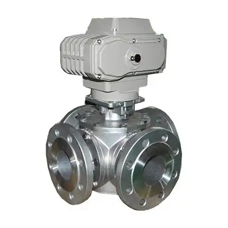
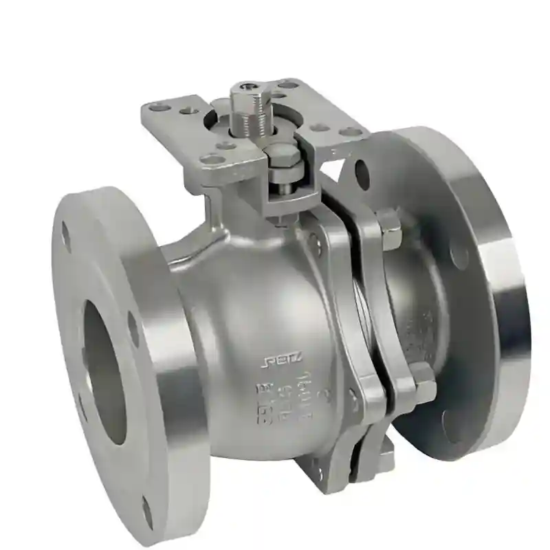
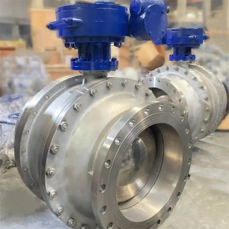
The 8″ 3 way ball valve is a large‑bore three‑way ball valve with nominal size 8‑inch (DN200). Rotation of its internal ball enables flow switching, diversion and media confluence within main process pipelines. Boasting a flow‑coefficient Cv value generally above 2000, this size is widely adopted in oil‑and‑gas gathering manifolds, power‑plant circulating‑water circuits, main pipelines of large‑scale water‑treatment facilities, and district cooling‑heating trunk networks.
Compared with conventional assembly schemes consisting of multiple 2‑way ball valves plus large‑bore T‑fittings, its core advantage lies in functional integration. A single 8‑inch three‑way ball valve delivers three‑way diversion duties that otherwise demand two large‑size 2‑way valves plus assorted pipe fittings. It cuts flange or weld joints from more than 10 down to merely 2‑3, reducing potential leak points by 60%‑80%. Within large‑bore piping systems, every flange joint represents a potential leakage source and maintenance hotspot. Fewer flange connections translate to lower leakage hazards, reduced routine inspection workload and enhanced overall system reliability.
Structural Advantages Through Reduced Leak Points
Large‑bore piping systems (8‑inch and above) commonly adopt flanged or butt‑weld end connections. A typical switching assembly built with two 2‑way ball valves and one T‑fitting contains 8‑12 flange joints. By contrast, one single 8″ 3 way ball valve only requires three flanged connections (one inlet plus two outlets); butt‑weld ends further bring joint quantity down to two.
During long‑term service, large‑size flange joints are far more prone to leakage caused by thermal cycling, pipeline vibration or bolt‑creep relaxation than valve‑body sealing surfaces. Fewer flange connections directly mitigate leakage risks. Meanwhile, it cuts down the number of positions requiring bolt retightening and leak inspection during routine patrols, as well as the quantity of gaskets to be replaced during major overhauls.
Material & Construction
Valve‑body materials are selected according to specific service conditions:
- ASTM A216 WCB (cast carbon steel): For water, oil, gas and general‑purpose industrial applications
- ASTM A351 CF8M (316L stainless steel): For corrosive media and seawater service
- Ductile Iron: For medium‑low‑pressure water‑treatment and municipal water‑supply‑drainage scenarios
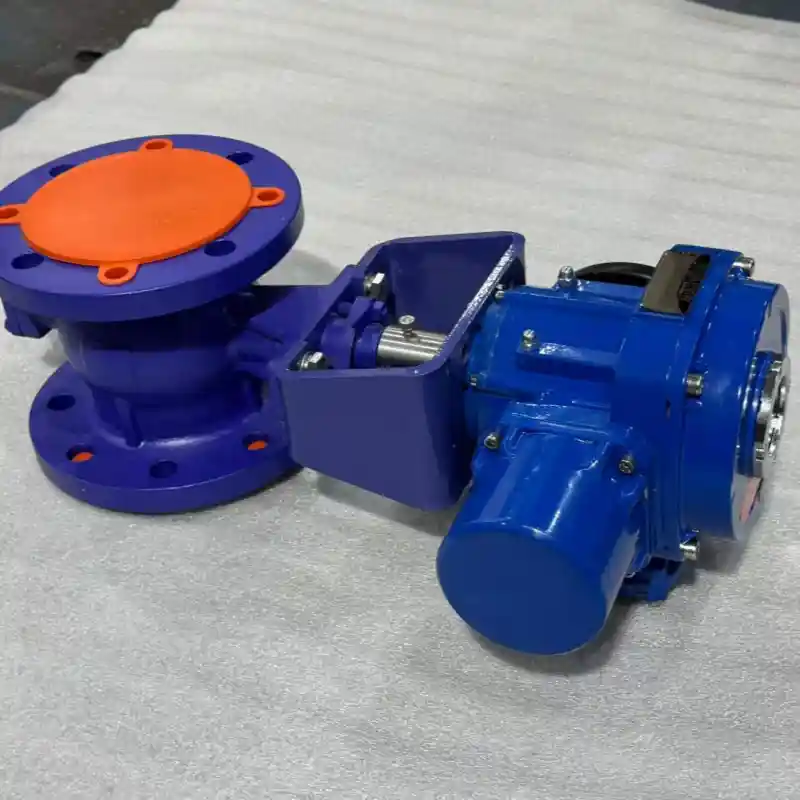
Large‑bore units come fitted with standard gearbox actuation to substantially cut operating torque.
Specifications & End Connections
| Parameter | Specification |
|---|---|
| Nominal Size | 8 inch (DN200) |
| End Connection | Flange (ANSI Class 150 / 300 / 600 RF/RTJ) / Butt Weld |
| Pressure Class | Class 150 / 300 / 600 (max. 1,480 PSI) |
| Temperature Range | ‑29°C ~ 180°C (PTFE seat) / ‑29°C ~ 250°C (PEEK seat) |
| Flow Pattern | L‑Port (flow switching) / T‑Port (mixing & diversion) |
| Body Material | WCB cast carbon steel / CF8M stainless steel / Ductile iron |
| Ball Material | 13Cr stainless steel / 316L stainless steel |
| Seat Material | Reinforced PTFE / PEEK |
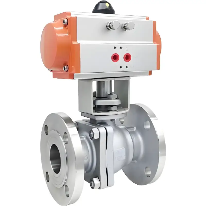
| Operation Mode | Gearbox (standard) / Pneumatic actuator / Electric actuator |
| Flange Standard | ANSI B16.5 / EN 1092‑1 |
| Design Standard | ASME B16.34 / API 6D |
Flow‑Pattern Selection Guidance
- L‑Port: Directs incoming flow to one of two alternative outlet ports, suited for flow‑direction change‑over, bypass modulation and filter back‑wash switching.
- T‑Port: Splits one inlet stream into two outlet branches, or merges two incoming flows into a single discharge port for mixing and diversion duties.
Typical Application Sectors
- Oil & gas gathering: Bypass switching for pump‑station / compressor‑station circuits, branch‑line diversion and inlet change‑over for standby process units
- Power‑industry circulating‑water systems: Main‑pipe switching for circulating cooling water within thermal‑power and nuclear‑power plants
- District cooling & heating networks: Main‑branch point switching for city‑scale chilled‑hot water distribution grids
- Large‑scale water‑treatment plants: Main‑line switching and flow distribution for water‑works and wastewater‑treatment facilities
- Heavy‑duty industrial cooling circuits: Chilled‑water trunk‑line switching for hyperscale data centres and large commercial building complexes
Reference Application Case
The project for main distribution manifolds at PUB Changi NEWater Reclamation Plant (Case 3), one of Singapore’s largest NEWater facilities with a treatment capacity of 218 000 cubic‑metres per day. Its 8‑inch main‑distribution pipelines required sequenced diversion of reclaimed NEWater to diverse end‑user zones including industrial consumers, commercial premises and municipal water‑make‑up networks. The original layout deployed gate valves combined with pipe fittings; each switching point assembled multiple gate valves alongside large‑bore T‑fittings, generating over ten flange‑groove joints with considerable leakage risks and cumbersome manual operation workflows.
CHCV 8″ 3 way ball valves were adopted as the solution, featuring L‑Port geometry, ductile‑iron body, full‑port bore, gearbox operation and grooved ends. Each switching point replaced the intricate multi‑valve manifold with one standalone three‑way ball valve. Flange‑groove joint count dropped from above 10 down to three (one inlet plus two outlets), cutting leak‑point quantity by 70%. Full‑port internal geometry guarantees zero capacity bottlenecks for the plant’s 218 000 m³/d throughput, with negligible hydraulic pressure loss. Following commissioning, no water‑supply outages triggered by valve‑or‑joint leakage have occurred on main distribution manifolds. Previously multi‑person co‑ordinated operating procedures are simplified to single‑operator manual manipulation.
Quality Assurance
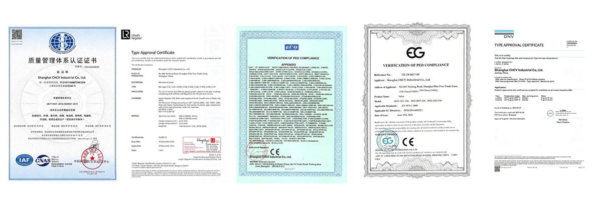
This product complies with API 6D pipeline‑valve requirements and ASME B16.34 design specifications. API 607 fire‑safe certification is available as an optional scope, while anti‑static devices are supplied as standard. Every large‑bore valve undergoes 100% hydrostatic shell‑strength testing and bidirectional seat‑tightness verification. Gearbox operators carry IP65 ingress‑protection rating, well‑suited for outdoor field installation.