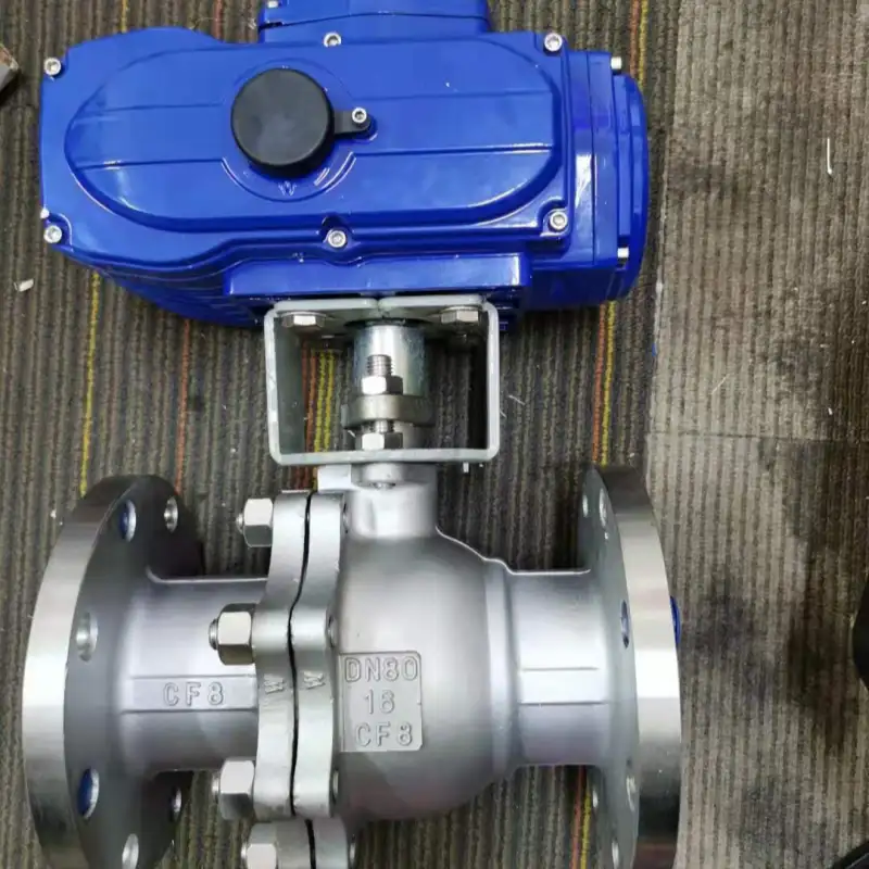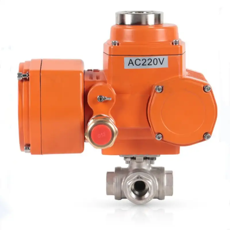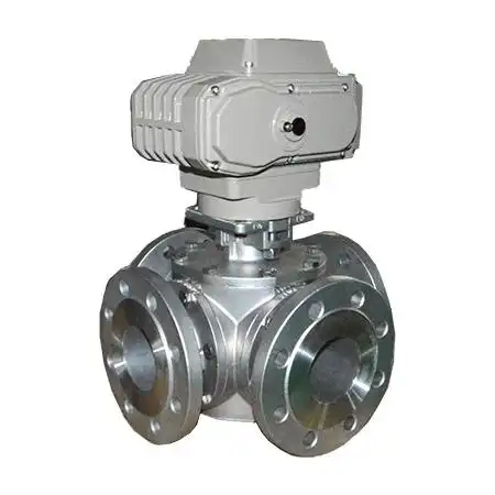

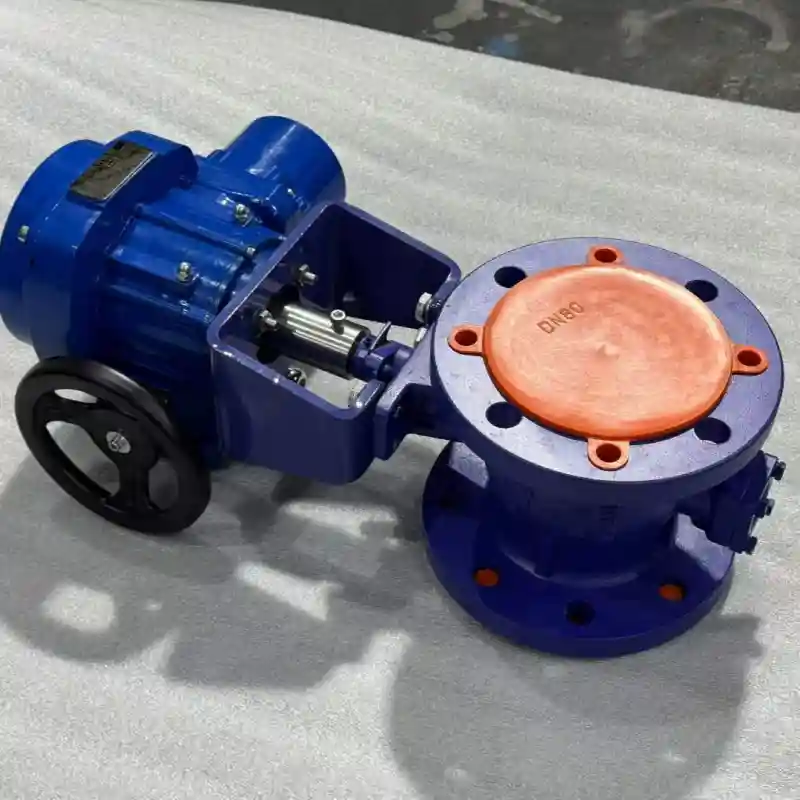
Solid Ball Valve for High-Temperature Slurry and Wax Services
Solid ball valve eliminates internal cavity deposition in waxy slurries. Used in Yanchang coal-to-liquid project. DN200, 280°C, 3.5MPa. Request your quote.
Description
In coal chemical processing, oil sands extraction, and heavy hydrocarbon upgrading, pipeline streams often carry solid particles, paraffin wax, or highly viscous components. These materials tend to accumulate and harden inside the hollow cavities of conventional ball valves, leading to rising operating torque or even seizure.
The solid ball valve addresses this problem with a dense, monolithic metallic sphere—forged or cast as a solid entity without any internal voids or weight‑reducing bores. This design fundamentally eliminates retention spaces within the ball, making it a dedicated shut‑off valve for abrasive, sticky, or waxy services.
Structural Advantages and Operating Principle
The essential difference between a solid‑ball valve and a conventional hollow‑ball design lies in the compactness of the sphere. From a mechanical standpoint, the solid ball offers several benefits:
-
No media entrapment – The ball surface is a continuous solid metal body. When closed, any fluid trapped in the body cavity cannot enter the ball interior. This prevents overpressure from vaporisation at high temperatures and avoids rupture from freezing at low temperatures.
-
Absence of stress concentration – Hollow balls have internal corners and lightening holes that act as stress raisers, where fatigue cracks may initiate under cyclic loading. A solid ball has no such structural discontinuities, providing superior fatigue resistance.
-
Higher inertia and precise positioning – With a uniform mass distribution and greater rotational inertia, the solid ball is less prone to overshoot or rebound caused by fluid impact when the actuator or manual operator stops. This yields better positional stability compared to hollow‑ball designs.
Materials and Specifications
| Parameter | Specification |
|---|---|
| Nominal Diameter (DN) | DN15 – DN600 (½″ – 24″) |
| Pressure Rating | Class 150 – Class 2500 |
| Body Material | A216 WCB / A105 / F316 / F51 Duplex / 4140 Alloy Steel |
| Ball Material | Solid forged (no cavities), matching body material + surface hardening |
| Ball Structure | Fully dense metal, no lightening holes or internal chamber |
| Seat Material | Reinforced PTFE / PEEK / Metal‑to‑Metal (hard‑seated) |
| End Connections | Flanged (RF/RTJ) / Butt‑Weld (BW) |
| Actuation | Manual Lever / Gearbox / Pneumatic / Electric |
| Design Standards | API 6D / ASME B16.34 / ISO 17292 |
| Anti‑static | Standard (per API 608) |
| Suitable Media | Solids‑laden slurries, high‑viscosity liquids, paraffin, asphalt, coal slurry, etc. |
Typical Applications
-
Heavy wax and slurry lines in coal‑to‑liquids (Fischer‑Tropsch) units
-
Oil sands production and bitumen transport pipelines
-
Vacuum residue and heavy fuel oil lines in refineries
-
Mine tailings and concentrate slurry conveying systems
-
High‑pressure, high‑cycle services where positioning accuracy is critical
-
Cryogenic low‑temperature conditions (to eliminate liquid trapping risks)
Field Case – Yulin Coal‑to‑Liquids Project, Shaanxi Yanchang Petroleum Group
In the Fischer‑Tropsch synthesis unit of this project, a heavy wax slurry line (DN200, 280 °C, 3.5 MPa) carries a stream from the reactor to the wax separator, containing approximately 35 % solid paraffin particles and catalyst fines. Originally, a hollow‑ball valve was installed. After 18 months of service, an internal inspection revealed that the ball’s internal cavity had become filled with a 2‑cm‑thick hardened mass of wax and catalyst, causing uneven mass distribution and a 40 % increase in operating torque—accompanied by noticeable sticking during actuation.
During a scheduled turnaround in 2021, the valve was replaced with a solid‑ball type, featuring a one‑piece forged 4140 alloy steel sphere with no internal voids. After more than three years of continuous operation, periodic borescope inspections have shown only superficial scoring on the ball’s outer surface, no significant deposit accumulation in the body cavity, and operating torque remaining within ±5 % of the design value. The project’s equipment management department has since cited this replacement as a best practice in their internal technical bulletins, recommending that solid‑ball valves be given preference for highly waxy or solids‑laden services.
Selection Guidelines
When selecting a solid ball valve, pay special attention to the following three points:
-
Ball weight and support structure – The solid ball typically weighs 1.8–2.5 times more than its hollow counterpart. For large diameters (DN400 and above), extra care is needed during transport, lifting, and installation—confirm that the valve’s bottom support structure and the associated piping have adequate load capacity.
-
Operating torque behaviour – The higher rotational inertia of a solid ball creates more pronounced inertial effects during start/stop cycles compared with hollow balls. When equipping with electric or pneumatic actuators, verify that the braking and cushioning systems are properly sized to achieve precise positioning without overshoot.
-
Cavity cleaning interval – Although the solid ball eliminates internal ball‑cavity deposits, the annular space between the ball and the body can still accumulate solids. It is advisable to perform cavity inspections at the 3‑month and 6‑month marks after first commissioning, then establish a routine cleaning schedule based on actual findings.