








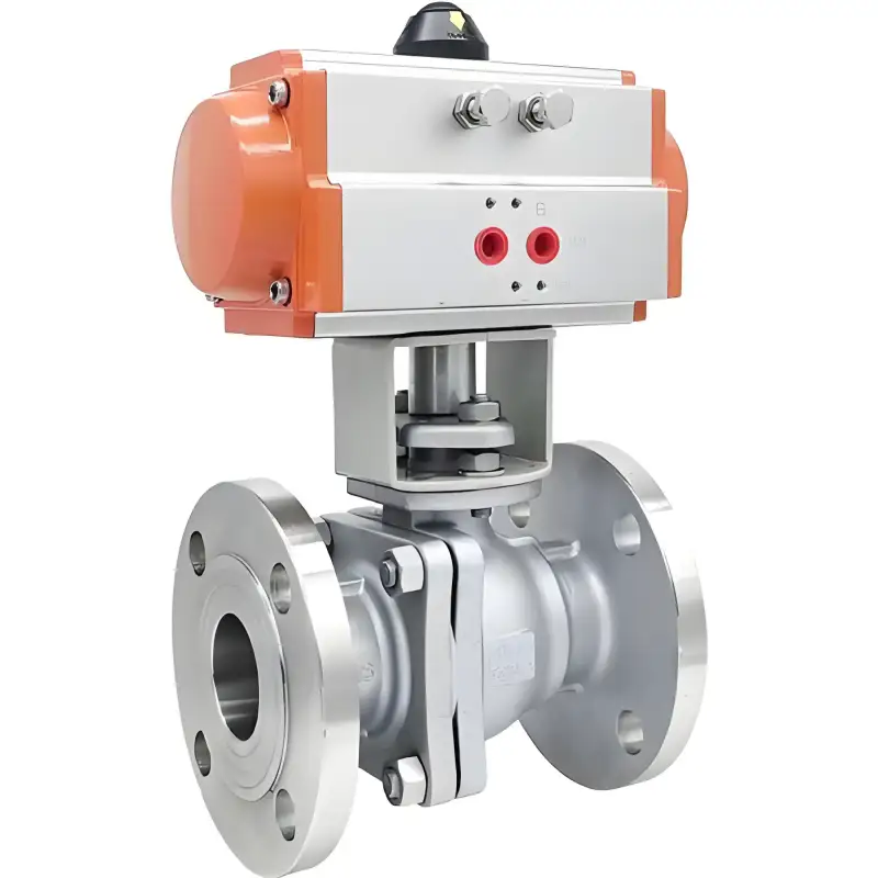
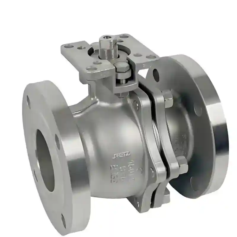
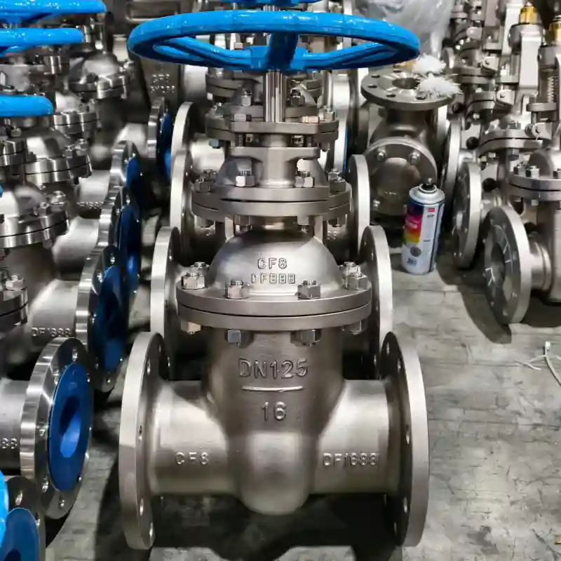
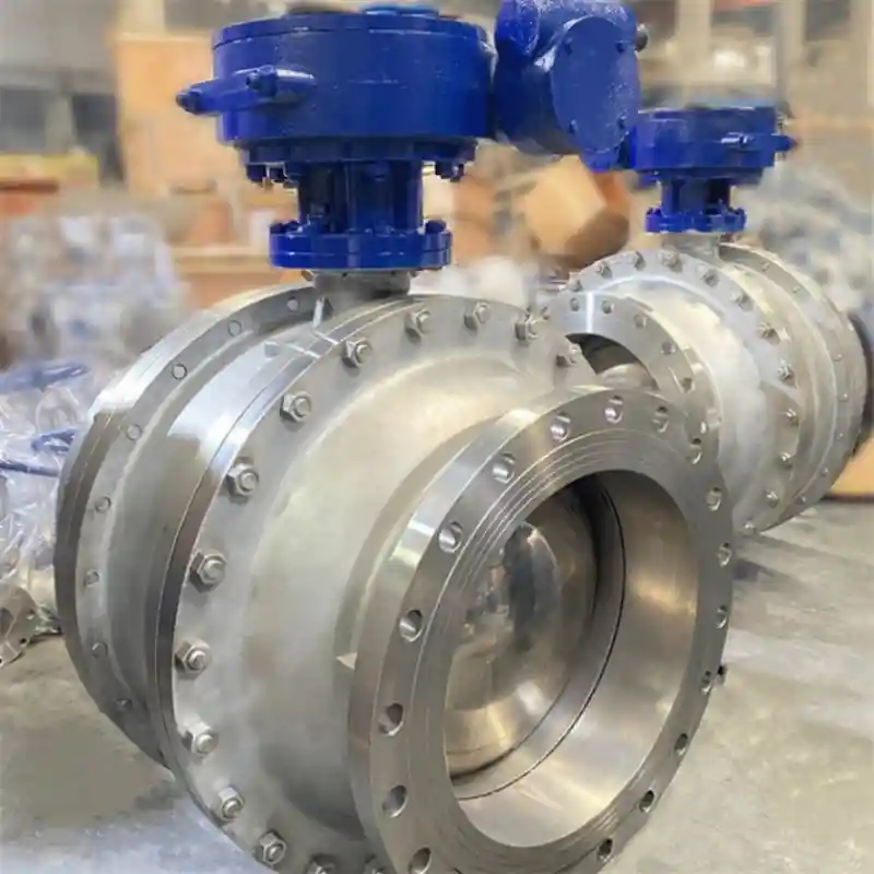
Reducing Ball Valve for Pump Discharge and Compact Pipe Racks

Reducing ball valve combines pipe size transition and shut-off in one body. Used in Denver Water’s Moffat WTP. DN400×DN200, space-saving. Request a quote.

Description

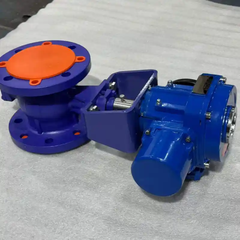
In piping systems, when a process line must transition from a larger diameter to a smaller one while also incorporating a shut‑off function, the conventional approach is to install a separate reducer fitting and an isolation valve in series, joined by two flanged or welded connections. This two‑component assembly not only increases the overall axial length but also introduces additional potential leak paths. A reducing ball valve consolidates both the size transition and the shut‑off capability into a single body – the inlet end carries the larger flange size, the outlet end the smaller one, and the ball passage is machined with a conical taper from the full inlet bore down to the reduced outlet bore. A single installation thus accomplishes both diameter reduction and flow isolation, making it an ideal choice where installation space is at a premium.

Design and Material Construction

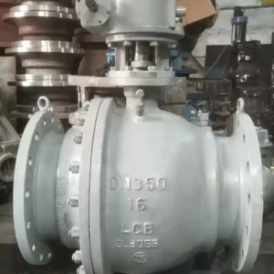
The reduction section of the reducing ball valve is integrally cast or forged with the valve body, forming a smooth conical internal flow passage that eliminates the flow disturbances – such as steps, misalignments, and weld beads – often found in field‑assembled reducer‑plus‑valve combinations. Body materials can be selected from carbon steel (ASTM A216 WCB / A105), stainless steel (CF8M / F316), or duplex stainless steel (F51 / F53), depending on service conditions. The ball is manufactured from matching material and subjected to surface hardening treatments; sealing pairs are available in reinforced PTFE or metal‑to‑metal configurations. A permanent flow arrow is cast on the exterior of the body (from the larger inlet to the smaller outlet) to clearly indicate the required installation orientation. End connections are offered in flanged styles (RF, FF, RTJ) or butt‑weld (BW) to accommodate various piping standards.

Key Technical Specifications

Parameter Specification
Inlet size (DN) DN50 – DN600 (2″ – 24″)
Outlet size (DN) DN25 – DN400 (1″ – 16″), inlet larger than outlet
Pressure rating Class 150 – Class 2500 / PN10 – PN420
Body material WCB / CF8M / F316 / F51 duplex / Hastelloy
Ball material Same as body + hard facing (Stellite / tungsten carbide)
Seat material Reinforced PTFE / PEEK / metal‑to‑metal
End connection Flanged (RF/FF/RTJ) / Butt‑weld (BW)
Actuation Manual lever / gearbox / pneumatic / electric
Design standard API 6D / ASME B16.34 / ISO 17292
Flow direction Unidirectional (large inlet → small outlet), body arrow provided
Pigging compatibility Not permitted (due to outlet reduction)

Application Areas

  • Pump discharge lines where the pump outlet diameter exceeds the downstream piping size.

  • Compressor and reciprocating pump pulsation dampening lines.

  • Compact pipe layouts within skid‑mounted packages.

  • Branch lines from flocculation basins to sedimentation basins in water treatment plants.

  • Firewater main to sprinkler branch take‑offs.

  • High‑pressure gas manifold outlets requiring diameter reduction before downstream equipment.

Case Study – Denver Water’s Moffat Water Treatment Plant

During the expansion of the Moffat Water Treatment Plant, operated by Denver Water in Colorado, a DN400 influent line from the flocculation basin needed to supply a DN200 backwash water branch to the sedimentation basins. However, the filter gallery had a clear height of only 2.4 metres – insufficient for a conventional reducer‑plus‑ball‑valve assembly in the vertical orientation. The engineering team instead selected a DN400×DN200 reducing ball valve, which integrated the eccentric reducer and the shut‑off valve into one unit. This solution reduced the overall installed height by approximately 160 mm compared with the conventional approach, allowing the piping to fit within the available gallery space. In their project close‑out report, Denver Water’s project manager noted that the integrated design also minimised the number of flanged joints in the gallery, thereby lowering long‑term leakage risks. The valve has been in reliable service since its commissioning in 2022, with no operational or accessibility issues reported.

Selection Guidelines

When specifying a reducing ball valve, pay particular attention to the following:

  1. Directionality – the valve is designed for unidirectional flow, with the larger bore at the inlet and the smaller at the outlet. The body arrow must align with the actual flow direction; reverse installation will compromise sealing integrity.

  2. Pigging prohibition – because the outlet is reduced in diameter, pipeline pigs cannot pass through this valve. It must not be specified for any pipeline section that requires routine pigging operations.

  3. Slurry or solids‑laden media – if the process fluid contains a significant concentration of solid particles, consider an eccentric reducing ball valve instead, as its offset design reduces solids deposition and erosion at the transition zone.