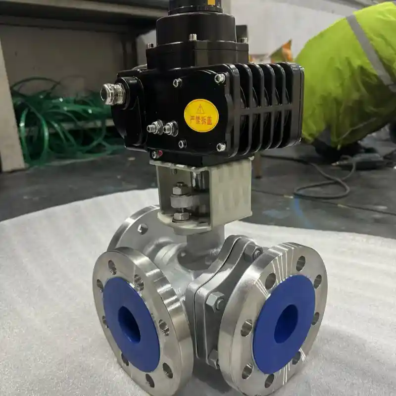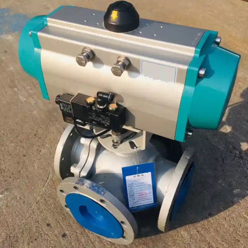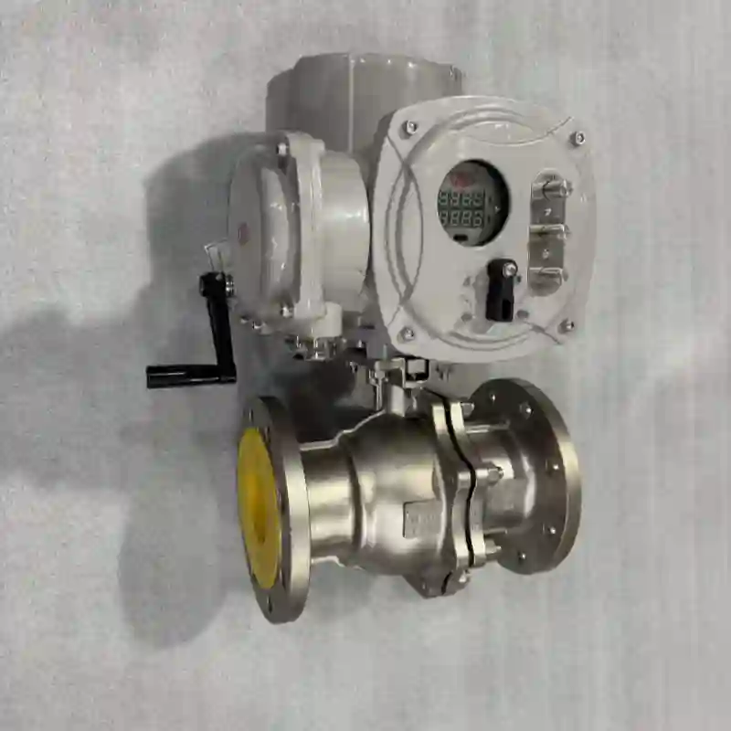

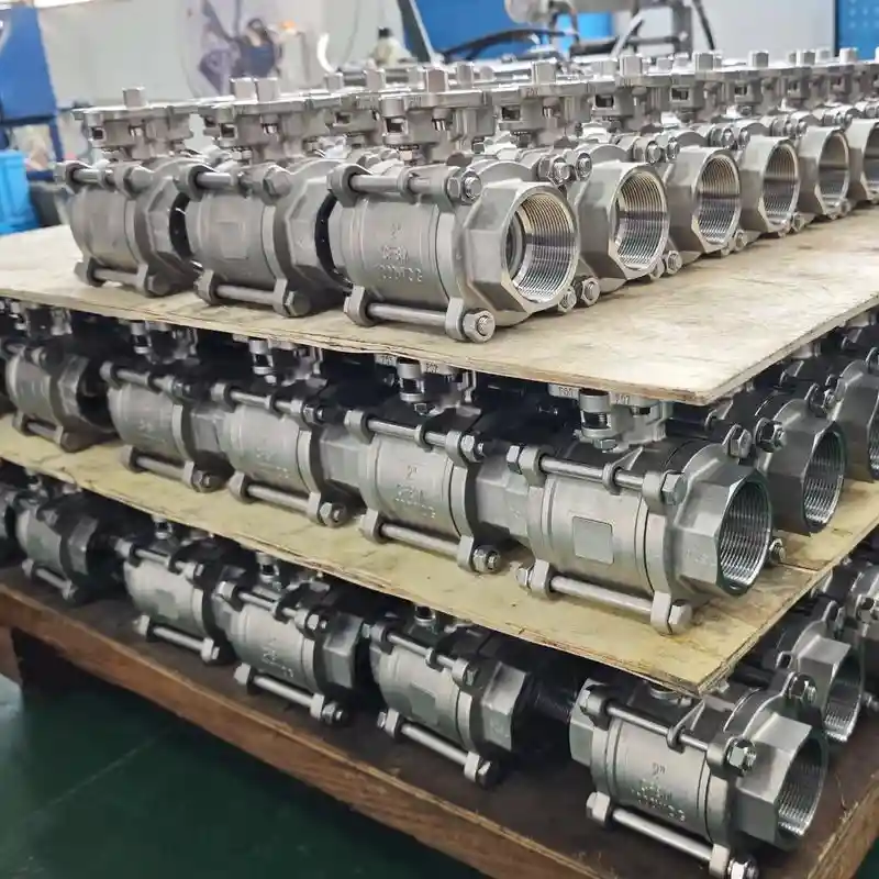
3 Piece Floating Ball Valve – Low Torque Class 150-600
3 piece floating ball valve with pressure-assisted sealing, low operating torque, and 3-piece body for in-line maintenance. Class 150-600, DN15-DN200, stainless/carbon steel.
Description
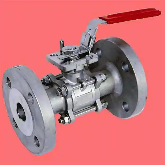
A 3 piece floating ball valve comprises three independent components‑left‑hand body, central body and right‑hand body‑fastened together by bolts. The ball sits within the valve cavity and is supported by seats on both sides, without dedicated bearing supports. Rotated 90° by the stem, the ball enables media shut‑off and flow passage.
It operates on a pressure‑assisted self‑sealing principle: process pressure acts against the upstream face of the ball and pushes it toward the downstream seat. Higher system pressure generates greater contact pressure between ball and seat, boosting sealing performance as media pressure rises. Thanks to its three‑piece layout, technicians can extract the central cartridge to replace seats and balls on‑site without removing the complete valve from piping, enabling in‑line maintenance.
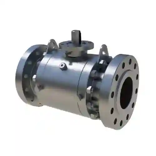
Floating‑type ball valves have defined application limits: DN ≤ 200 and Class ≤ 600. Beyond this envelope, ball weight plus axial thrust induced by process pressure will drive sharp increases in operating torque and seat wear. Under such conditions, trunnion mounted ball valves should be specified instead.
Material and Specification
| Parameter | Specification Range |
|---|---|
| Valve Body | WCB (carbon steel) / CF8 (304) / CF8M (316) / 316L |
| Ball | Body‑equivalent material / 316L |
| Stem | 316L / 17‑4PH |
| Seat | PTFE / RPTFE / TFM / EPDM / PEEK |
| Nominal Size | DN15 ~ DN200 (1/2“ ~ 8”) |
| Pressure Class | Class 150 / 300 / 600 |
| End Connection | Flange (ASME B16.5 / EN 1092‑1) / Butt weld / Socket weld / Thread (NPT/BSPT) / Tri‑Clamp |
| Body Design | Floating type — ball supported by bilateral seats |
| Sealing Principle | Process pressure pushes ball against downstream seat (pressure‑driven self‑sealing) |
| Operating Torque | Increases with differential pressure; lower than trunnion‑mounted valves of identical size |
| Face‑to‑Face Standard | ASME B16.10 / EN 558 |
| Anti‑Blow‑Out Stem | Standard configuration |
| Actuator Mounting Platform | ISO 5211 direct‑mount platform (optional) |
| Material Certificate | EN 10204 3.1 (available upon request) |
Structural Features: Floating‑Sealing Mechanism and In‑Line Servicing
The floating‑driven sealing concept constitutes the key differentiator between 3 piece floating ball valve and trunnion‑mounted counterparts.
Pressure‑powered self‑sealing: In the closed position, upstream process pressure bears against the ball and forces it onto the downstream seat. Seats, typically manufactured from PTFE or reinforced polymer compounds, deform elastically under ball thrust and form tight conformal contact with the spherical surface. A defining trait of this mechanism is that sealing contact force scales automatically with system pressure. Sufficient sealing load is maintained under low‑pressure service, while proportionally elevated contact pressure preserves tight shut‑off at higher working pressures.
Reduced operating torque: During opening and closing cycles, friction between ball and seat originates primarily from process‑pressure‑derived thrust acting on the ball. For equivalent nominal size and pressure class, floating‑style ball valves generally demand lower actuation torque compared with trunnion‑mounted variants, which carry extra frictional losses from bearings and seat spring preload. This advantage permits selection of compact pneumatic or electric actuators, cutting capital expenditure and saving installation footprint within automated skids.
In‑line maintenance via three‑piece construction: Prolonged service may introduce creep or wear within PTFE or EPDM seats, gradually diminishing sealing performance. The three‑piece architecture allows maintenance crews to pull out the central cartridge on‑site for seat renewal without full‑valve disassembly. Servicing can be completed rapidly with no overhead lifting equipment required.
Application Scenarios
3 piece floating ball valves are widely deployed within medium‑and‑low‑pressure process piping: ‑ Food & beverage: CIP circuits, syrup, dairy and beer pipelines subject to frequent cycling under low‑pressure conditions ‑ Chemical industry: Medium‑and‑low‑pressure acid, alkali and solvent lines (Class 150‑600) ‑ Pharmaceutical sector: Purified‑water, buffer‑solution and non‑sterile API distribution piping ‑ Water treatment: RO reverse‑osmosis loops, circulating cooling water and municipal water‑supply networks ‑ Oil & gas: Medium‑and‑low‑pressure gathering lines for natural gas, crude oil and produced water
Field Application Case
Within the fermentation‑hall CIP cleaning system at AB InBev (Brouwerijplein 1, 3000 Leuven, Belgium), 3 piece floating ball valve units serve as isolation valves that distribute cleaning media to individual fermenters. This brewery is the birthplace of Stella Artois, hosting over 40 fermentation tanks. The CIP installation executes 2‑3 automatic cleaning cycles daily, delivering 85 ℃ caustic soda solution, hot water and acid detergent. Valves range from DN40 to DN80 with Class 150 pressure rating, SS304 wetted components and Tri‑Clamp connections. EPDM seats are selected for superior alkali‑resistance and thermal stability relative to PTFE. Each valve is fitted with a pneumatic actuator governed by PLC‑based automation.
Operating pressure for the CIP loop sits at 0.4‑0.6 MPa, representing typical low‑pressure service. The floating‑valve self‑sealing principle generates adequate seating contact within this operating envelope; EPDM seats deflect elastically under mild ball thrust to establish reliable shut‑off. Thanks to low actuation‑torque characteristics, compact 40 Nm pneumatic actuators were specified. Comparable trunnion‑mounted valves of equal size would ordinarily require actuators rated 60 Nm or higher. Downsized actuators yield measurable savings in compressed‑air consumption. Site energy‑management records indicate roughly 25 % lower compressed‑air demand for the updated CIP circuit versus the former trunnion‑valve‑based setup.
From a reliability perspective, contact stress across EPDM seats is governed by process pressure rather than spring preload. Seat loading exists only during valve closure and is relieved when the valve opens, mitigating cumulative permanent compression‑set damage to EPDM material. Commissioned during the 2018 CIP‑system retrofit, these valves accumulated more than 20 000 switching cycles by the end of 2025 across over seven consecutive years of runtime.
Only two preventive seat replacements were performed, at the fourth‑ and sixth‑year service intervals respectively. Both interventions adopted the three‑piece in‑cartridge‑pull‑out workflow: technicians loosened central‑body bolts on‑site along the pipe rack and extracted the middle assembly for EPDM seat renewal, while end‑side Tri‑Clamp connections remained untouched. Each seat‑replacement task consumed approximately 30 minutes. Internal plant‑equipment assessments compiled by the fermentation‑plant maintenance supervisor ranked 3 piece floating ball valves as the most consistently performing, lowest‑maintenance valve type deployed across the site’s CIP infrastructure.