
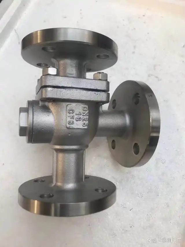
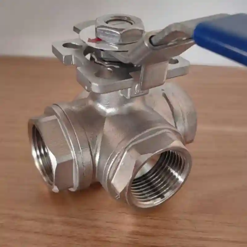
Three-Way Ball Valve for Closed-Loop Water Systems – Low Leak Risk
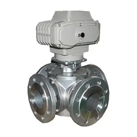
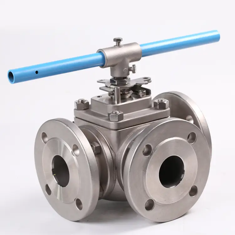
Three-way ball valve for closed-loop water systems in bronze/SS316, L-port and T-port. Full port minimizes pressure drop, one-valve design reduces leak points. Ideal for HVAC, district cooling, and data center cooling.
Description
A three‑way ball valve for closed‑loop water systems is purpose‑engineered for closed circulating‑water circuits. Ball rotation enables flow diversion, bypass regulation or zone‑based splitting for supply‑return piping loops. Such circuits are widely found within HVAC central air‑conditioning, district cooling / heating, data‑centre cooling and industrial process cooling installations, where strict requirements apply for long‑term sealing stability, low fugitive‑emission rates and minimal flow resistance.
Its core advantage over conventional assemblies built from multiple two‑way ball valves plus pipe fittings is that one single three‑way ball valve handles all flow‑control duties at one switching node. Welded or flanged joint quantities drop from six or more down to 2‑3, cutting potential leak points by 60%‑75%. Within closed‑loop water circuits, every leak source brings water loss, extra energy consumption for makeup pumps and potential equipment damage. Reduced joint count therefore directly improves long‑term system operational reliability.
Design Mechanism for Mitigated Leakage Risks
In closed circulating‑water installations, leakage mainly originates from pipe connection joints and stem sealing interfaces. This product incorporates targeted optimizations for these two vulnerable locations:
‑ Minimized joint quantity: Traditional “two‑way valve plus fittings” configurations require two valves paired with multiple T‑fittings and elbows, typically generating 6‑10 welded or threaded joints. By integrating all flow passages inside one valve body, this unit only needs two end‑connections (inlet and outlet), delivering a 60%‑75% joint reduction. Since every joint constitutes a potential leak source, fewer connections lower long‑term leakage probability and cut the number of positions requiring routine leak inspection.
‑ Low‑emission stem sealing: A triple‑barrier stem assembly combining dual O‑rings and low‑emission PTFE packing is adopted. Verified under EPA Method 21 test procedures, external fugitive emission stays below 100 ppm, satisfying low‑emission specifications for closed‑loop water service. Wear‑resistant sealing compounds withstand dozens of actuation cycles per day without developing wear‑induced leakage.
‑ Durable seat sealing: Reinforced PTFE seats mate with precision‑polished stainless‑steel balls to deliver Bubble‑tight Shut‑off in closed position for both flow directions. PTFE features excellent hydrolysis resistance and chemical inertness. It maintains stable performance in circulating water mixed with ethylene‑glycol / propylene‑glycol antifreeze agents and corrosion inhibitors, avoiding swelling or contraction‑triggered leakage caused by fluctuating water chemistry.
Material and Construction
Body materials are selectable according to system water chemistry and pressure requirements:
‑ Nickel‑plated Brass: Cost‑effective option for small‑to‑medium size (≤2″) commercial‑building HVAC circuits.
‑ Ductile Iron / WCB Cast Steel: Intended for large‑bore (≥2.5″) main piping within district cooling / heating networks.
‑ Bronze / SS316 Stainless Steel: Deployed for seawater cooling or chemical process circulating loops demanding superior corrosion resistance.
Balls are manufactured from SS304 / SS316 stainless steel; seats are reinforced PTFE, and stem sealing relies on dual O‑ring plus PTFE packing combination.
Specifications & End Connections
| Parameter Item | Specification Details |
|---|---|
| Nominal Size | 1/2″ ~ 6″ (DN15 ~ DN150) |
| End Connection | NPT thread / BSP thread / ANSI Class 150 flange / Socket Weld / Butt Weld |
| Pressure Rating | 600 PSI WOG (cold water) / 300 PSI Steam (hot water) |
| Temperature Range | 0°C ~ 120°C (PTFE seat) |
| Flow‑Port Variant | L‑Port (flow switching) / T‑Port (mixing or diverting) |
| Body Material | Nickel‑plated brass / Ductile iron / WCB cast steel / CF8M stainless steel |
| Ball Material | SS304 / SS316 stainless steel |
| Seat Material | Reinforced PTFE |
| Stem Seal | Dual O‑ring + PTFE packing (low‑emission design) |
| Operation Type | Manual lever / Lockable handle / Pneumatic actuator / Electric actuator |
Flow‑Port Selection Guidance
‑ L‑Port: Optimized for diverting one circulating‑water inflow between two separate outlet branches. Typical use‑cases include supply‑return bypass switching for chillers, mode transition between plate heat exchangers and chillers, plus cooling‑tower circuit re‑routing.
‑ T‑Port: Suited for merging two circulating‑water streams into one discharge, or splitting one incoming flow into two outputs. Representative applications cover temperature adjustment via cold‑hot water blending and cooling‑capacity distribution across different building zones.
Typical Application Sectors
This valve demonstrates proven field performance within the following closed‑loop water environments:
‑ HVAC Central Air‑Conditioning Systems: Chiller supply‑return bypass switching to sustain minimum evaporator flow under partial‑load conditions and prevent coil freezing.
‑ District Cooling / Heating: Mode switching between primary and secondary networks inside heat‑exchange stations, enabling seasonal transition between cooling and heating service.
‑ Data‑Centre Cooling Systems: Fluid re‑routing between chillers and plate heat exchangers to realize automatic toggle between mechanical cooling and Free Cooling operating modes.
‑ Industrial Process Cooling Circuits: On‑off and isolation switching for cooling‑water supply to discrete equipment such as injection‑moulding machines, welding units and air compressors.
Reference Application Case
For a heat‑exchange‑station project belonging to Danfoss A/S within the district‑cooling network of Copenhagen, Denmark (Case 3), three‑way ball valve for closed‑loop water systems units (L‑Port, full‑port bore, duplex‑stainless‑steel body, butt‑weld ends, PEEK seats) were installed on mode‑switching manifolds for the secondary distribution network.
Copenhagen’s district‑cooling infrastructure ranks among Europe’s largest, delivering service to over 100 000 end‑users. Multiple large‑scale heat‑exchange stations form the network. At each station, the secondary Closed‑Loop Distribution Side requires seasonal switching between plate‑heat‑exchanger cooling mode and direct chiller‑cooling mode. Switching nodes are sized at 3‑inch, operating at 130 PSI with seasonal water‑temperature variation ranging from 6°C to 45°C.
The original design adopted two 3‑inch two‑way ball valves paired with one T‑fitting via butt‑weld connections for each switching point, generating six welded joints per node. Across 42 heat‑exchange stations, total welded joints exceeded 250. Though welds avoid flange‑related leak risks, every weld joint required X‑ray non‑destructive inspection, bringing high testing expenditure and long lead‑times. Defect repairs also incurred substantial costs; inspection and rework expenses once accounted for 15 % of this sub‑system’s total budget.
After retrofitting with three‑way ball valves, welded joints per switching node fell from six down to two (only butt‑weld ends at valve body), representing a 65 % reduction in weld count. Corresponding X‑ray inspection points and repair‑risk locations decreased accordingly. Meanwhile, full‑port geometry combined with precision‑polished balls keeps secondary‑side pressure drop below 0.3 PSI under switched modes without disturbing hydraulic balance across the district‑cooling network. Overall weld‑inspection costs dropped by roughly 40 %, and construction timelines were shortened by three weeks. Following commissioning, two complete cooling seasons (around 24 months) of field operation recorded zero system outages triggered by weld‑joint leakage or valve internal seepage. The end‑user has incorporated this valve type into technical procurement specifications for all future heat‑exchange‑station builds.
Quality Assurance
The product complies with ASME B16.34 design standards, with optional API 607 fire‑safe certification. Low‑emission stem sealing passes EPA Method 21 laboratory validation. Every valve undergoes 100 % hydrostatic shell‑strength testing plus bi‑directional seat tightness inspection prior to shipment, guaranteeing sealing reliability for long‑term closed‑loop water‑system service.