
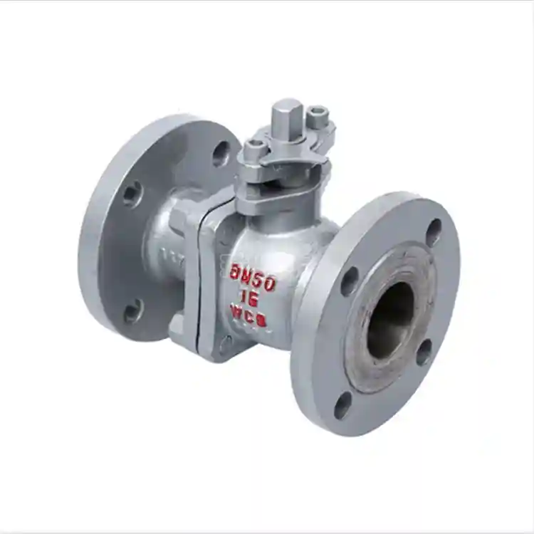
1 1/2″ Flanged Ball Valve Carbon Steel Body – WCB, Class 150-600
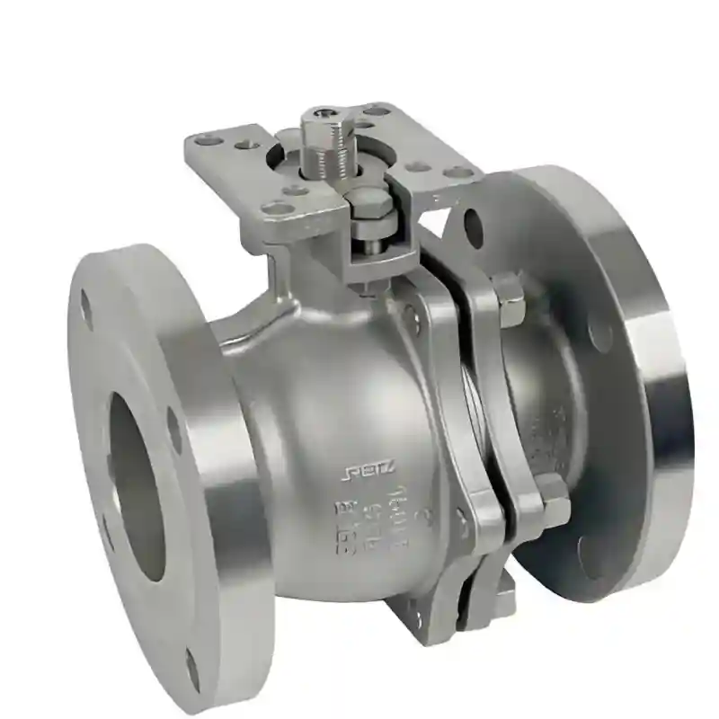
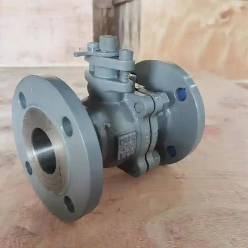
1 1/2″ flanged ball valve carbon steel body with WCB material, RF flange ends, Class 150-600. Bolt-on design for quick maintenance and pipe layout changes.
Description
The 1 1/2″ Flanged Ball Valve Carbon Steel Body is an industrial shut‑off valve with nominal size DN40 (1.5‑inch) and flanged end connections. Body materials are ASTM A216 WCB cast steel or ASTM A105 forged steel. Flange faces are manufactured in accordance with ASME B16.5, offering RF raised‑face, FF flat‑face and RTJ ring‑joint‑face configurations. Pressure classes cover Class 150, Class 300 and Class 600. Falling in the transition range between small‑bore threaded valves and large‑size flanged valves, this rating fits piping with wall thickness of Sch 40 and above. It sees extensive service on low‑flow branch lines and equipment inlet‑outlet circuits across refining, chemical, natural‑gas, power‑generation and district‑heating sectors.
II. Flanged Joint and Ease of Disassembly
Flanged connection constitutes its key distinction from threaded and welded alternatives. Unlike threaded ends, flanged joints require no thread machining on pipe ends, thus avoiding wall‑thickness reduction caused by threading. For thin‑walled Sch 40 piping, threading often demands further material removal to achieve adequate thread depth, whereas flanged connections preserve the original pipe wall thickness in full. Compared with socket‑weld or butt‑weld ends, flanged joints are fully demountable: valves can be isolated from piping simply by loosening flange bolts. This feature proves especially valuable under three sets of operating conditions:
- Scheduled maintenance: Valves fitted at equipment nozzles require off‑line inspection or replacement aligned with equipment turnaround cycles. Flanged units enable rapid removal without pipe cutting or re‑welding.
- Process modification: During plant revamps or piping layout adjustments, flanged ball valves may be dismounted entirely and reinstalled at new locations for repeated service. Welded valves, by contrast, become scrap once cut out.
- Gasket servicing: Flange gaskets are consumable components subject to periodic replacement. Gasket renewal on flanged assemblies only involves loosening bolts, extracting old gaskets, fitting new ones and retightening, with no hot‑work required.
For this specific 1.5‑inch size, flanged joints bring an extra practical benefit: bolt counts are typically four for Class 150 and eight for Class 300 / 600. Tightening and dismantling workload remains moderate, making handling lighter and faster compared with flanged valves 2‑inch and larger.
III. Material Specifications and Design Standards
ASTM A216 WCB cast steel serves as the standard body material, rated for −29 °C to 425 °C. ASTM A105 forged steel shares the identical temperature envelope as an alternative. Balls are produced from AISI 304 or 316 stainless steel. Seat sealing options include PTFE (−29 °C‑150 °C), RPTFE (−29 °C‑180 °C) and PPL (−29 °C‑260 °C), with PPL suited for high‑temperature steam and hot‑oil duties.
Flange dimensions comply with ASME B16.5, with RF (most common), FF (for mating with cast‑iron flanges) and RTJ (for high‑pressure Class 600 and above) face types. Face‑to‑face dimensions follow ASME B16.10: 178 mm short‑pattern for Class 150 and 191 mm for Class 300. The stem adopts anti‑blow‑out construction. Anti‑static hardware satisfies API 608 requirements, while API 607 / 6FA fire‑safe features are available as an optional scope.
IV. Field Case Demonstrating Disassembly Advantages
This is exemplified in a replacement project for heat‑exchanger isolation valves at Shell’s Moerdijk Lubricant Blending Plant. Heat exchangers undergo chemical cleaning every six months, during which inlet‑outlet valves need removal for off‑line inspection. Originally fitted butt‑weld ball valves required weld cutting, re‑beveling and re‑welding for every removal‑reinstallation cycle. Each valve took more than six man‑hours to handle, together with welder qualification checks, hot‑work permits and non‑destructive testing.
In 2019, the plant retrofitted all sixteen heat‑exchanger inlet‑outlet positions with 1.5‑inch carbon‑steel flanged ball valves (Class 300, WCB body, RF flange face). During subsequent cleaning campaigns, complete disconnection of each valve after bolt loosening takes merely 12 minutes, and reassembly plus flange bolting finishes within 20 minutes. Maintenance supervisors reported that the overall turnaround for heat‑exchanger cleaning shrank from four days down to 1.5 days. Pipefitters can execute the full workflow independently without welder support or hot‑work approval. Across four successive cleaning cycles, these valves have been repeatedly demounted and refitted. Flange bolts and gaskets stay in sound condition with no thread damage or sealing‑face scratching observed.
V. Technical Specification Sheet
| Parameter | Specification Range |
|---|---|
| Nominal Size | DN40 (1 1/2″) |
| Pressure Class | Class 150 / 300 / 600 |
| Cast‑Steel Body Material | ASTM A216 WCB |
| Forged‑Steel Body Material | ASTM A105 |
| Ball Material | AISI 304 / 316 Stainless Steel |
| Seat Material | PTFE / RPTFE / PPL |
| Flange Standard | ASME B16.5 |
| Flange Face Type | RF / FF / RTJ |
| Face‑to‑Face (Class 150) | 178 mm (ASME B16.10) |
| Face‑to‑Face (Class 300) | 191 mm (ASME B16.10) |
| Bolt Quantity | 4 pcs (Class 150) / 8 pcs (Class 300/600) |
| Anti‑Static Feature | API 608 |
| Fire‑Safe Compliance | API 607 / API 6FA (optional) |
| Design Codes | ASME B16.34 / API 6D |
| Operating Temperature | −29 °C ~ +260 °C (seat‑material dependent) |
| Process Media | Water, steam, oil products, natural gas, mildly corrosive fluids |
VI. Typical Application Scenarios
- Small‑bore piping at equipment nozzles in refineries and chemical plants requiring periodic maintenance
- Inlet‑outlet isolation valves for heat‑transfer equipment including heat exchangers, coolers and condensers
- Shut‑off valves for vent and blow‑down lines at natural‑gas gathering stations
- Small‑size bypass circuits for boiler feed‑water and drain systems in power plants
- Equipment‑side isolation valves for fuel‑oil and lube‑oil branch piping on marine vessels
- Sectionalising valves on end‑user branch circuits within district‑heating networks
- Sampling and blow‑down systems in process units subject to frequent piping‑layout revisions
VII. Selection and Installation Guidance
When specifying 1.5‑inch carbon‑steel flanged ball valves, verify that mating pipe flanges share the identical standard (ASME, DIN or JIS) and pressure class; flanges built to different standards cannot be directly coupled. Ensure flange‑face types match on both sides (RF‑to‑RF, RTJ‑to‑RTJ). Tighten flange bolts in a cross‑torquing pattern in two to three incremental passes. Final torque values shall reference ASME PCC‑1 Appendix A or the manufacturer’s torque tables. Keep flange sealing faces clean and scratch‑free during installation. Select gasket grades compatible with process temperature and corrosivity: PTFE gaskets suit most non‑corrosive services, while graphite‑composite gaskets apply for high‑temperature steam.