3 Way Ball Valves are widely used in piping systems for flow splitting, flow combining, flow diversion and bypass service. Visually, they look like 2-way ball valves with an extra port, yet their internal ball flow path, seat loading, handle limit stops and actuator control logic are all different.
Below is an explanation covering definition, operating process, L-port / T-port flow paths, installation direction prohibitions and selection criteria.
What Is a 3 Way Ball Valve? What Is a Three Way Ball Valve?
What is a 3 way ball valve?It is a ball valve with three ports on the valve body. Rotating the perforated ball changes the communication status between the three ports.
What is a three way ball valve?It can be understood as a valve that switches flow paths via a ball: medium enters the ball bore and flows out from different outlets or merges with another stream depending on the ball rotation angle.
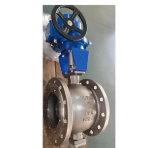
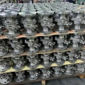
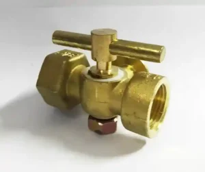
A typical 3 way ball valve consists of valve body, ball, stem, seats, end caps, handle or actuator. End connections include threaded, flanged, welded, clamped and others. Material options include brass, stainless steel 304/316, carbon steel, PVC, UPVC, CPVC, etc.
Pressure ratings include 1000 WOG, PN16, Class 150, Class 300, 3000 psi and so on.
It is NOT simply a 2-way ball valve with an added port. The shape of the ball bore and port functions determine whether the valve serves for diversion, splitting or combining.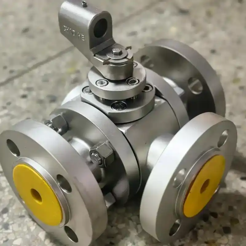
3 Way Ball Valve Working Principle: How Ball Rotation Changes Flow Paths
The core of the 3 Way Ball Valve Working Principle lies in the ball. The stem inserts into a slot on top of the ball, and seats clamp the ball to form sealing.
When the handle or actuator turns the stem, the ball rotates between the seats. Ports aligned with the ball bore are open; ports blocked by the solid section of the ball remain closed.
Take L-port type as an example. Its ball bore is L-shaped, normally connecting two adjacent ports while the third port remains closed. Rotate the handle by 90°, and it switches to connect the other pair of adjacent ports. For T-port type, the ball bore is T-shaped. It can connect all three ports or two ports only; certain designs can close multiple ports at specific positions. T-port is suitable for splitting, combining and bypass applications, while L-port is better for diversion.
During rotation, the ball bore and ports will go through partial overlap. This state creates throttling, pressure drop and elevated local flow velocity. If the medium contains particles or is prone to crystallization, the partially overlapped position may accelerate wear on sealing surfaces.
Therefore, 3 way ball valves are generally used for switching and splitting service. They are NOT recommended to stay partially open for long-term operation as control valves.
3 Way Ball Valve L Port T Port Diagram: L-port and T-port Flow Path Drawing
When reviewing the 3 Way Ball Valve L Port T Port Diagram, confirm port numbering first. Most 3 way ball valves have two coaxial ports and one side port, marked A, B, C. The bore of an L-port ball is like a right-angle bend; it can only connect two adjacent ports and cannot interconnect all three ports at the same time. The bore of a T-port ball resembles the letter T, enabling communication among all three ports or between two opposite ports.
L-port and T-port cannot be distinguished merely by external appearance. If the system requires two inlet streams merging into one outlet, T-port is usually required. If the system needs one inlet to switch between two outlets, L-port is preferred. Using an L-port valve in place of a T-port will result in one port failing to open or close properly. Using a T-port valve in place of an L-port may cause incorrect split flow ratios and ambiguous closed positions.
When confirming 3 way ball valve orders, CHCV requires customers to provide port connection drawings, medium, temperature, pressure, L-port or T-port selection, handle position or actuator control scheme. This avoids on-site rework caused by misunderstanding of flow path diagrams.
3 Way Ball Valve Positions: Handle Angle, Port Status and Actuator Limit Stops
3 Way Ball Valve Positions are not limited to simply “open” and “closed”. L-port models usually have multiple 90° positions corresponding to different adjacent port combinations. T-port models may have states including all three ports interconnected, two ports interconnected, or partial ports shut off. Handle orientation relates to ball bore direction, yet marking conventions vary by manufacturer. Do NOT judge port status only by whether the handle is parallel or perpendicular to the pipeline.
Electric or pneumatic 3 way ball valves require attention to actuator travel. 2-way ball valves commonly use 90° actuators, while 3 way ball valves may need 90°, 180° or multi-position control.
Directly mounting a 2-way actuator onto a 3 way ball valve may lead to incorrect limit settings, ball failing to reach sealing position, actuator over-torque or wrong position feedback. ISO 5211 mounting flange, limit cams, feedback switches and wiring diagrams must match the port functions of the valve body.
Can 3-Way Ball Valves Be Installed Backwards? Installation Restrictions and 3 Way Ball Valve Flow Direction
Can 3-way ball valves be installed backwards?The answer is not a simple yes or no. Some 3 way ball valves feature body, ball and seat designs for bi-directional sealing, capable of withstanding pressure regardless of flow direction. However, “medium can flow in both directions” does NOT equal “reverse installation is acceptable for the system”. 3 Way Ball Valve Flow Direction shall be determined by port functions, actuator limit stops, bleed holes, seat structure and process flow.
If a flow arrow is cast on the valve body, install the valve following the arrow. Without flow marking, install per port numbering, P&ID or manufacturer port diagrams. For splitting applications, which port is used as inlet and which two serve as outlets will affect flow path and pressure drop.
For combining applications, swapping two inlets and one outlet may change flow distribution. If an L-port diversion valve is mounted backwards, the outlet corresponding to each handle position will change, leading to operator misjudgment.
Installation prohibitions include:
- Stem permanently pointing downward: particles in medium tend to deposit near packing area; actuators mounted upside down are also not recommended.
- Electric actuator mounted downward or sideways beyond specification: compromises limit function and protection rating.
- Welded 3 way ball valves welded without removing ball or end caps: heat will damage PTFE, RPTFE and other seals.
- Over-tightening threaded ends: may deform valve body.
- Large-size valves without pipe support: pipeline stress transfers to valve body.
- Applying 2-way actuator and 2-way handle position drawing directly to 3 way ball valves.
For 3 way ball valves with bleed holes, cavity pressure relief structure or single-sided seat preload, reverse installation can alter seat loading, resulting in internal leakage, external leakage or inability to release cavity pressure.
If reverse installation is mandatory on site, confirm valve body structure, port functions, actuator travel and sealing direction with the manufacturer in advance.
CHCV 3 Way Ball Valve Selection & Inquiry Checklist
When contacting CHCV for 3 way ball valve quotation, please provide the following information:
- Port quantity and end connection type
- L-port or T-port
- Manual, electric, pneumatic or with feedback
- Medium name, temperature and pressure
- Valve body material and seal material
- Required flow direction or port interconnection table
- Installation space and stem orientation
- Flanged, threaded, welded or clamped ends
- Whether test certificates such as API 598, ISO 5208 are required
CHCV can supply port diagrams, handle position drawings, actuator wiring diagrams and installation instructions for 3 way ball valves. For splitting, combining, diversion and bypass service, confirm flow path drawing first, then valve body material, seal material and actuator control scheme. This approach is more reliable than only specifying nominal size and pressure class.
Conclusion
The operating principle of 3 way ball valves relies on ball rotation to change port communication. L-port is used for switching between adjacent ports; T-port is used for splitting, combining and bypass applications.
During installation, do not only check dimensions and threads. Verify 3 way ball valve flow direction, port numbering, L/T flow path, handle position and actuator limit stops. Can 3-way ball valves be installed backwards?If the valve body is bi-directional and the system permits, medium may flow in reverse. However, if port functions, bleed structure, seat orientation or actuator limit stops have specific requirements, reverse installation introduces operational and sealing risks.
Contact CHCV for 3 way ball valve drawings and selection support.