
Many plumbing and small industrial piping retrofit projects select the Apollo 3/4 ball valve. Even with reliable product quality, improper installation can cause thread stripping, body leakage, and premature failure of internal sealing components.
Drawing from on-site piping operational experience, this article fully outlines the complete workflow for this size ball valve, from pre-installation verification, assembly procedures to final commissioning testing. It also covers how to select compatible replacement ball valves when the original brand has supply constraints.
3/4 inch brass ball valve dimensions: Verify basic parameters of valve body and piping before installation
Before starting work, do not directly torque the threads. Complete valve and piping verification first; this step prevents most rework issues later.
- Visual and functional inspection of the valve body. After unpacking, visually check the valve body for cracks or dents caused by transit impact. Manually cycle the handle back and forth to confirm the ball valve switches smoothly between fully open and fully closed positions without binding or loose play. If the handle turns sluggishly, do not proceed with assembly — the seals or ball may have sustained damage during shipment.
- Check valve body outline dimensions. Refer to the 3/4 inch brass ball valve dimensions specifications to confirm overall body length and face-to-face distance, and measure reserved space on-site for the piping. If clearance is limited, the handle may be blocked by walls or fittings after installation, preventing normal operation later.
- Preparatory treatment for the piping system. Shut off upstream media supply, vent internal pressure and drain residual media from the pipe. Clean pipe connections to remove rust, leftover old PTFE tape residue and welding slag. Fine hard particles entering the valve cavity can scratch the ball and seat sealing surfaces, creating hidden risks of internal leakage.
- Service condition compatibility confirmation. Check the pressure and temperature marked on the valve nameplate to verify suitability for the process media (potable water, compressed air, gas, etc.).
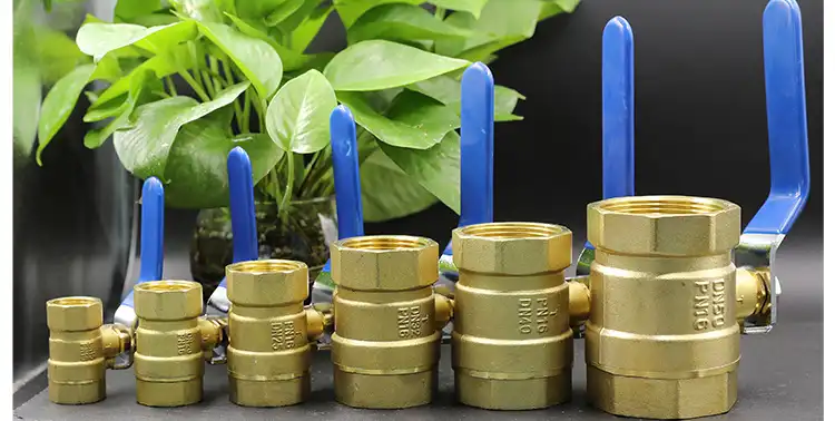
Sourcing note: If procurement of the Apollo 3/4 brass ball valve faces delivery delays, the CHCV 3/4 brass ball valve can be used as an alternative. When selecting the replacement, also verify outline dimensions, connection specifications, rated pressure and temperature to ensure full compatibility with existing piping space and service conditions. The connection size and pressure class of the CHCV two-piece brass ball valve fit most plumbing piping applications originally designed for the Apollo 3/4 ball valve.
3/4 inch ball valve thread standard: Confirm thread specification to avoid forced assembly
The 3/4 inch ball valve thread standard is one of the most common pitfalls for threaded ball valves. Even with the same nominal 3/4 size, products use NPT American tapered pipe thread, BSPP / BSPT British pipe thread. These thread forms and tapers are incompatible; forcing them together will directly damage the threads.
- Check the marking engraved on the Apollo valve body to confirm whether it uses NPT or BSP threads. Also verify the thread standard on the pipe end; both must match. Do not judge visually. Use a thread gauge for measurement if available.
- Wrap PTFE tape only on male threads, following the rotational direction of tightening. Apply 3–4 wraps only. Do not push tape fragments into the valve cavity at the thread root. Debris trapped inside can jam the ball sealing surface and cause failure to shut off tightly and internal leakage.
- Thread the valve onto the pipe by hand first. It should engage smoothly for several turns when hand-tight. If it is already tight when hand threading, stop immediately and investigate mismatched threads or burrs. Never use a wrench to force it on.
Field tip: Assembling threads for two-piece brass ball valves requires a two-wrench method. Secure the valve end near the pipe with one wrench and turn the pipe fitting with the second wrench. Do not apply force directly to the central body joint of the valve. Excessive torque can pry open the seam of the two-piece valve body and cause leakage at the body joint. Once tightened, do not back off the valve to reposition the handle orientation. Backing off breaks the PTFE tape seal. If handle alignment adjustment is needed, reassemble by adding or removing wraps of PTFE tape.
3/4 ball valve installation common mistakes: Avoid frequent installation failures
Based on a large number of field repair cases, nearly all leaks and valve body damage related to 3/4 ball valve installation common mistakes stem from preventable human operating errors.
- Excessive torque causing body cracking. Brass has limited hardness. Many installers follow the misconception that “tighter means leak-proof” and keep increasing wrench torque, generating invisible microcracks at threaded ports. These cracks may not show moisture initially but seep gradually under fluctuating line pressure and are difficult to locate. For a 3/4 brass threaded ball valve, after hand-tight engagement, an additional 1–1.5 turns of tightening is sufficient. Rely on tactile feedback where possible, or use a torque wrench.
- Pipe stress transferred to the valve body. Without proper pipe supports, the valve bears bending and shear loads from pipe dead weight and thermal expansion. Even if the threaded joint stays leak-free right after assembly, seepage will develop over time. Pipe hangers or supports shall be fitted on both sides of the valve so that piping loads are carried by supports instead of the valve.
- High heat damaging internal seals during brazing/welding. For weld-end 3/4 ball valves, keep the valve fully open during welding and apply heat shielding or cooling to the middle section of the valve body. Avoid prolonged flame impingement on the main valve body. PTFE seat seals have limited heat resistance and lose sealing performance once melted.
- Insufficient handle operating clearance after installation. Valves fitted tight against walls or elbows can restrict the handle from completing the full 90° stroke, leaving it partially open. Long-term throttling service accelerates seal wear from media impingement on the ball.
Replacement note: If the original Apollo valve fails from body cracking or thread damage, installing the CHCV 3/4 brass ball valve must follow the same error avoidance rules above. A new valve can still be damaged by improper installation practices.
3/4 ball valve pressure test after installation: Pressure testing upon completion of installation
Do not place the system into service directly after mechanical assembly. Perform the 3/4 ball valve pressure test after installation to verify both external and internal sealing integrity.
- Confirm the handle can fully cycle between open and closed positions without obstruction, and adjacent pipe supports are secured.
- External leak test (valve fully open). Set the valve to fully open, pressurize the piping slowly up to operating pressure and hold. Visually inspect both threaded joints and the valve body seam for beads of water or damp seepage.
- Internal leak test (valve fully closed). Switch the ball valve to fully closed, maintain upstream pressure, and check the downstream outlet. Continuous media flow on the downstream side indicates internal leakage across the ball and seats. Internal leakage is usually caused by foreign debris entering the valve cavity during installation; the valve will require disassembly for cleaning or replacement.
- After depressurization, cycle the ball valve 3–5 times, then repeat a simple hold-pressure test to confirm stable sealing after repeated operation.
- Once all tests pass, clear the work area, mark the valve open/close direction and complete installation.
Summary
Check dimensions and thread standards before installation; control tightening torque and eliminate incidental piping stress during assembly; carry out pressure testing after completion to reduce future maintenance.