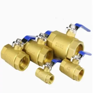

How to wire a motorized ball valve cannot be answered safely by a generic online color chart. Wiring depends first on rated voltage, control mode, terminal definition, and whether open/closed feedback is provided. Actuators with similar housings can have different movement logic when their wire counts differ.
Before wiring, obtain the exact model wiring diagram and terminal table. Confirm power, control signal, feedback contacts, and protection devices separately. Do not connect a power wire to a control terminal merely because the terminal looks similar.
For model and connection details, see CHCV valve resources.
how to wire an electric ball valve: Lock down four information groups first
The first step in how to wire an electric ball valve is confirming four groups: supply voltage, on/off or modulating control, terminal numbers, and feedback contacts. De-energize the circuit while checking the nameplate and drawing, then confirm that the control cabinet output can handle actuator starting current and that the work follows site electrical-safety rules.
3 wire ball valve wiring: Separate movement from feedback during acceptance
Acceptance for 3 wire ball valve wiring is more than seeing the valve turn. Confirm that open, closed, or running feedback is recognized by the controller, that the position indicator agrees with actual flow isolation, and that power loss and re-energization states are recorded. Do not short feedback wires simply because they are not being used temporarily.
🛠️ Five checks before wiring
- Model and voltage: Nameplate, order, and power supply agree.
- Terminal definition: Power, control, and feedback are identified separately.
- Protection: Isolation, grounding, and site electrical rules are addressed.
- Movement test: Jog, full open, and full close are checked one by one.
- Readback record: Cabinet status agrees with the valve indicator.
📌 Case Setting
Status Automation Technologies is an industrial-automation service company in Petaling Jaya, Selangor, Malaysia. It focuses on control-cabinet integration and field commissioning for small and medium-sized factories. For a utility upgrade, Status Automation had to organize control-cabinet wiring for electric ball valves on several branches. Some branches used basic on/off valves, while others used models with one-to-one open/closed feedback. The team found that the most likely error was carrying one color convention across different models and mixing a power wire from an on/off valve with a signal wire from a feedback-equipped valve.
To remove that risk, the team listed each valve model, working voltage, terminal number, control mode, and feedback state. It tested movement direction on a bench first, confirmed that the open command produced the intended rotation and feedback, and only then connected each valve to the matching cabinet terminal. Unconfirmed wire colors and terminal numbers were left blank until CHCV supplied the formal wiring and terminal-definition documents for each model. CHCV supplied the electric ball valves and complete wiring information, supporting the quality-control path from bench testing to cabinet connection.
how to wire a 3 wire ball valve: Do not guess from wire colors
How to wire a 3 wire ball valve cannot be replaced by a fixed “red positive, black negative, white signal” rule. A three-wire arrangement may use power and a common control, or it may define direction or feedback differently. Follow the terminal names and manufacturer drawing, and use a low-risk test to confirm open and close direction.
2 wire vs 3 wire motorized ball valve: Choose the control circuit
The 2 wire vs 3 wire motorized ball valve choice should reflect controller output and field-maintenance practice. Two wires may simplify the connection, but feedback and direction control depend on the model. Three wires add connection points but may provide separate control or feedback. Wire count alone does not establish which option is better.
3 wire motorized ball valve: Test jog, full open, and full close after power-up
After powering a 3 wire motorized ball valve, perform jog, full-open, full-close, and feedback tests in sequence. If the movement direction is wrong, de-energize the circuit and check the control logic; do not exchange conductors while energized. File the wiring diagram, terminal record, and test result with the equipment documents.
Frequently Asked Questions
Can three wires alone tell you how the valve should be wired?
No. Three wires describe the connection count, not the terminal functions. Confirm the common, control, and feedback terminals from the model-specific wiring diagram.
The valve moves after wiring, but feedback does not appear. What should be checked?
Check feedback-contact definition, controller input type, common terminal, and limit adjustment, then verify position direction. Do not troubleshoot by repeatedly energizing the valve without checking the circuit.