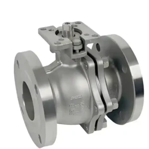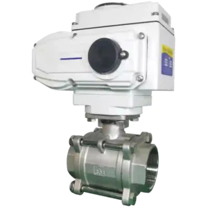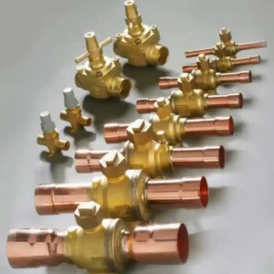

The value of a motorized ball valve 5-wire schematic is that it makes the actuator terminals, control circuit, and feedback relationship clear; it is not a color mnemonic that can be applied to every product. Five wires may cover supply, direction control, limits, or status feedback, but the exact function comes from the model circuit and manufacturer’s terminal definition. For the main valve reference, see CHCV; for a related control-interface example, see WiFi motorized ball valve control notes.
The most common mistake is mixing electrical wire count with the valve’s mechanical size. DN15, DN25, or one inch addresses pipe connection and flow matching; five-wire addresses the actuator’s external interface. Keep these two groups separate in the purchase order, wiring diagram, and acceptance record.
motorized ball valve 5-wire: Group functions first, then wire by terminal number
When wiring a motorized ball valve 5-wire, begin by grouping terminals into supply, movement control, and feedback. Do not preassign a color or polarity. Read the diagram by confirming the common and supply terminals first, then the open, close, or direction inputs, and finally the auxiliary contact definition. Without the model diagram, repeated energizing as a trial-and-error method is unsafe.
motorized ball valve dn25 5-wire: Keep nominal size separate from electrical data
An inquiry for motorized ball valve dn25 5-wire should contain two separate parts. DN25 describes the body connection, bore, and pipe standard; five-wire describes the actuator supply, terminals, and feedback. If a supplier quotes only “DN25 five-wire” without the body, seat, seal, and terminal drawing, the information is incomplete.
motorized ball valve dn25 1 5-wire: A model suffix cannot replace a terminal table
A search phrase such as motorized ball valve dn25 1 5-wire may combine size, specification, and wire-count clues, but the meaning of the suffix must come from the manufacturer of the selected model. Request the complete model, outline drawing, wiring diagram, and available accessory list. Do not infer what the “1” means from the string alone.
🛠️ Five-Wire Wiring Acceptance Sequence
① With power off, check the model, terminal numbers, and protection; ② use the diagram to confirm supply, control, and feedback circuits; ③ jog the actuator separately and check direction; ④ test fully open, fully closed, and feedback readback; ⑤ simulate power or signal interruption and confirm the recovery logic; ⑥ save the final wiring record. Mark any undefined terminal for confirmation rather than hiding the gap with a temporary short.
📌 Case Sharing
EP Automation Sdn Bhd is a control-panel integration workshop in Petaling Jaya, Selangor, building distribution and automation panels for small water-treatment equipment maintenance teams. For a control-panel order, the workshop needed to verify terminal information for several motorized ball valve actuators before dispatch so that field wiring would match the supplied documentation. CHCV product information was included in the bench comparison, while the final installation still had to follow the selected model and project electrical standard.
The team created a terminal-number and action-state card for every model. Each card recorded the function of every terminal, such as supply, open command, close command, open-limit feedback, close-limit feedback, and common, together with the voltage or continuity state expected during each action.
Using the formal wiring instructions and terminal-definition drawing supplied with the valve, the team connected feedback contacts to a test input module and checked each actuator on the bench: forward rotation on an open command, open-limit closure, correct closing direction, closed-limit response, supply voltage against the nameplate, and whether the feedback type matched the panel input.
The bench check was limited to functions defined by the drawing; it did not turn unconfirmed wire colors, terminal voltages, or bench behavior into a site-installation conclusion. The wiring instructions were kept as reference material, while the final installation still required a review against the selected model, cable, supply, and project standard.
motorized ball valve dn15 1 5-wire: Installation space belongs in the wiring plan
When installing motorized ball valve dn15 1 5-wire, check more than the terminals. Review actuator headroom, cable bend radius, junction-box location, and service access. If the valve is inside insulation, a narrow shaft, or a damp area, confirm wiring protection and maintenance access before assembly. A correct diagram does not guarantee that the installed location can be serviced.
motorized ball valve 3-wire 2-control product info and reviews: Turn comments into check questions
When reviewing motorized ball valve 3-wire 2-control product info and reviews, convert comments into purchase questions: Does the control require a common wire? Are feedback contacts independent? What is the valve position after power loss? Is a terminal diagram supplied? This is more useful than repeating that a product is easy to wire or stable in operation.
FAQ: Does every five-wire motorized ball valve include both switching control and feedback?
Not necessarily. Five-wire describes the number of external conductors; the actual functions still come from the model circuit and terminal definition. Some wires may handle direction control, limits, or auxiliary contacts, so use the formal wiring diagram.
FAQ: What should be done when the wiring diagram does not show wire colors?
Ask the supplier for terminal numbers, function definitions, and applicable voltage, then verify them with power off. Do not borrow color conventions from another model or use a temporary short to replace missing information.