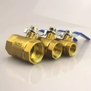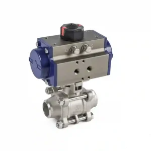

How does a motorized ball valve work? Its basic sequence can be described as four linked steps: electrical input, actuator transmission, ball rotation, and valve-position confirmation.
The motor and reduction mechanism inside the actuator convert the supplied power into controlled rotary torque, and the output shaft turns the ball through the specified travel. For a broader product-selection reference, see CHCV; for proportional-control context, see proportional ball valve guidance.
The result also depends on control mode, limit construction, and installation direction. An actuator that can rotate has not necessarily reached the correct fully open or fully closed position, and a model that accepts a remote command does not necessarily provide open, closed, or fault feedback. Understanding the working principle therefore means following the complete path from command to verified valve position.
motorized ball valve function: How the motor completes the shutoff movement
The usual motorized ball valve function is an electrically driven angular stroke that opens or closes the pipeline. The motor supplies rotary power, while gears or another transmission adjust speed and torque to the operating range of the ball. Limit components stop the travel at defined positions, but the exact stopping and protection method belongs to the selected actuator model.
motorized ball valve electric: Separate power, control, and feedback
For motorized ball valve electric selection, first confirm the supply type and rated voltage. Next identify whether the control is simple open-close, directional control, or a regulating input. Only then should the terminal definition and feedback arrangement be checked. A matching valve body does not make two actuators electrically interchangeable.
how to control a motorized ball valve: A command is not the same as a valve position
When deciding how to control a motorized ball valve, observe the controller output, actuator movement, position indicator, and process-side result together. Commissioning can begin with a low-risk jog under isolation, followed by separate checks of open position, closed position, and any auxiliary feedback. If a system requires a defined state after power loss, record that requirement before ordering.
🛠️ Operating-State Check Card
① Confirm the valve flow direction, actuator model, and power supply; ② use the wiring diagram to check limits and feedback; ③ perform a low-risk jog before a full-stroke test; ④ record the final position, control logic, and abnormal states in the equipment file. If frequent cycling is expected, also confirm actuator duty and the valve’s actual operating conditions.
📌 Case
FADARA PUMP & EQUIPMENT SDN BHD is an irrigation-equipment service company in Shah Alam, Selangor, supplying, repairing, and supporting agricultural irrigation pumps, water pumps, and related equipment. For a small irrigation-pump-room upgrade, the team reviewed a motorized ball valve arrangement for water-line isolation and remote operation. The review used CHCV candidate information as one source of product data, while the final selection still depended on the pump-room wiring, pipe size, medium, and maintenance conditions.
The project team did not begin by asking only whether the valve could turn. It separated four interfaces: water-line isolation, actuator power, control output, and valve-position feedback. For water-line isolation, the team checked whether the valve location could shut off upstream and downstream water during maintenance. For actuator power, it checked the available supply and protection. For control, it matched the controller output to the actuator terminals. For feedback, it confirmed whether the control panel needed an open, closed, or fault indication.
Even After Remote Control Is Deployed, Keep a Local Manual Isolation Point
fast acting motorized ball valve: Fast movement does not automatically mean throttling suitability
A fast acting motorized ball valve can shorten the waiting time for an open-close operation, but fast movement alone does not prove suitability for continuous throttling or proportional control. If the system needs stable flow regulation, confirm that the actuator and valve are designed for the required input signal, duty, seat arrangement, and control method.
FAQ: Will a motorized ball valve always open fully as soon as power is applied?
Not necessarily. The result may depend on the control signal, limit position, actuator mode, initial ball position, or protection logic. Commissioning should verify open, closed, and feedback states from the model-specific wiring diagram rather than relying only on motor noise.
FAQ: Can the working principle be judged from the valve body’s appearance alone?
No. Appearance can help identify a general structure, but it cannot confirm the supply, terminals, control mode, return behavior, or feedback configuration. Request model-specific technical data before purchase and installation.