
When selecting equipment for automated piping projects, people often search for “how does a pneumatic actuated ball valve work” to fully understand the entire transmission logic of pneumatic ball valves and determine whether they match the on-site working conditions.
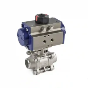
A pneumatic ball valve consists of two integrated parts: a pneumatic actuator and a ball valve body. It uses compressed air as the power source to perform a 90‑degree quarter‑turn on‑off action, thereby controlling the on/off of the pipeline medium.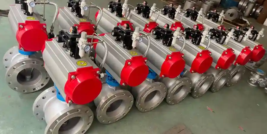
Double‑acting pneumatic ball valve working logic
A double‑acting actuator has two air inlet ports. Compressed air is alternately supplied to the two ports into the cylinder, pushing the piston and rack‑and‑pinion mechanism to convert linear thrust into rotational torque, which drives the valve stem and the ball to rotate. When the air supply reverses, the ball rotates 90° accordingly: when the ball’s bore aligns with the pipeline, the medium flows; when the solid side of the ball faces the flow path, the medium is shut off. In the event of air supply interruption, the double‑acting configuration does not automatically reset; the valve remains in the position it held before the air loss. This type is suitable for pipelines that require frequent on‑off cycling and do not need fail‑safe reset.
Single‑acting pneumatic ball valve working logic
Single‑acting, also known as spring‑return, has return springs built into the actuator cylinder. Compressed air enters the cylinder to overcome the spring force and drives the ball to open or close. Once the air supply is lost, the springs release their stored energy and push the piston back to its initial position, returning the valve to a preset fail‑safe position (fail‑open or fail‑closed). In industries such as chemical and oil & gas, where loss‑of‑air safety protection is critical, this type of ball valve is the preferred choice.
Special operating mode of 3‑way pneumatic ball valve
Unlike ordinary 2‑way ball valves, a 3‑way pneumatic ball valve has a ball with an L‑port or T‑port flow path. The actuator also receives compressed air to perform a 90° rotation, and the internal flow passages of the ball switch the medium flow direction, enabling flow diversion, merging, or reversal. This type is mostly used in multi‑loop fluid switching processes and cannot be used for high‑precision throttling control.
Accessory component: pneumatic ball valve with limit switch
A pneumatic ball valve with a limit switch has a feedback device mounted on the actuator exterior. When the valve reaches the fully open or fully closed position, the limit switch outputs an electrical signal to the PLC or DCS system, transmitting the valve’s actual position back to the control room. Operators can verify the valve status from the control room without going to the field for visual inspection. This is a common configuration for remote monitoring in automated pipelines.
Brief summary of the complete sequence: control system sends an electrical signal → solenoid valve switches the air direction → compressed air enters the actuator → piston and rack‑and‑pinion output torque → valve stem drives the ball to rotate 90°, completing the pipeline on/off action.
When selecting, do not only look at the working principle; you must confirm the actuator type, whether position feedback is needed, the flow path configuration, and match the pressure, medium, and safety requirements to avoid on‑site operational failures.